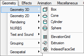
The following commands allow users to build primary 3D geometries: Box, Cone, Cylinder, Sphere, ElevationGrid, Extrusion, and IndexedFaceSet. The menu items shown in figure 1 and toolbar buttons in figure 2 are associated with these commands.
Figure 1 The primary 3D node menu items
![]()
Figure 2 The primary 3D node toolbar buttons
Each of these commands has following tasks:
A single separated 3D node not contained in a Shape node may be ignored by the X3D Browser in most cases, this is why each of these commands creates a Shape node.
Sections 1~6 explain how to use these primary 3D creation commands and how to edit these nodes and their fields; one following section specifies how to edit common properties; the last section specifies Boolean operations: Combine, Difference, Intersection, Exclusion, and Division.
These commands are accessible when editing X3D, Classic VRML, and VRML97 Models.
This command creates a Box node centered at (0, 0, 0) in a local coordinate
system and aligned with the coordinate axes; the box measures 2 units in each
dimension, from -1 to +1. The![]() toolbar button and the Box menu item are associated with the command.
toolbar button and the Box menu item are associated with the command.
In Design View, an activated or selected box has 8 points for editing the size field. When the cursor moves near a point, a small spot appears, which allows users to drag-and-drop. See figure 3(a). Check the Transformation section in Chapter Design View for further information.
![]()
Figure 3(a) A box and a small spot for drag-and-drop
In Tree View, to edit the size field values, follow the steps below.
Figure 3(b) shows a Box node Scene Graph.
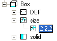
Figure 3(b) Editing the size field values in Tree View
This command creates a Cone geometry centered in a local coordinate system and
whose central axis is aligned with the y-axis; the cone has a radius of 1.0
at the bottom and a height of 2.0, with its apex at y = height/2 and its bottom at y = -height/2. The
![]() toolbar button and the Cone menu item are associated with this command.
toolbar button and the Cone menu item are associated with this command.
In Design View, an activated or selected cone has 5 small spots, which allow users to change the size.
See figure 4(a). When the mouse cursor moves near a point, drag-and-drop function is activated.
Check the Transformation section in Chapter Design View for further information.
![]()
Figure 4(a) A cone and its 5 small black spots for drag-and-drop operations
In Tree View, to edit the size, expand the
![]() tree branch if it collapses, then
tree branch if it collapses, then
Figure 4(b) shows a Cone tree list.
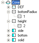
Figure 4(b) The Cone fields structure in Tree View
To set whether sides of the cone are created and displayed, set the side field value.
To set whether the bottom cap of the cone is created and displayed, set the bottom field.
Similar to the solid field, they can be edited in the Tree View. See the TRUE-FALSE box section for how to edit these fields.
The Cylinder command creates a capped cylinder centered at (0,0,0) in a
local coordinate system and with a central axis oriented along the y-axis.
The ![]() toolbar button and the
Cylinder menu item are associated with this command.
toolbar button and the
Cylinder menu item are associated with this command.
In a Design View, to edit the radius value, drag-and-drop the cylinder along the x- or z-axis; to edit the height, drag-and-drop the cylinder along the y-axis. Check the Transformation section in Chapter Design View for further information.
To set whether sides of the geometry are created and displayed, set the side field value; to set whether the bottom or top cap of the geometry is created, set the bottom or top value. Similar to the solid field, they can be edited in Tree View. See the TRUE-FALSE box section for how to edit these fields.
To edit cylinder size in Tree View, first expand the
![]() node item if it collapses, then
node item if it collapses, then
Figure 4(c) shows a Cylinder tree list.
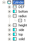
Figure 4(c) The Cylinder fields structure in Tree View
The Sphere command creates a unit sphere centered at (0,0,0) in a local
coordinate system. The
![]() toolbar button and the Sphere menu item are associated with this command.
toolbar button and the Sphere menu item are associated with this command.
In a Design View, to edit the radius value, drag-and-drop the geometry along any axis. Check the Transformation section in Chapter Design View for further information.
In Tree View, to edit the radius field value, follow the steps below.
Figure 4(d) shows a Sphere node tree branch.

Figure 4(d) The Sphere fields structure in Tree View
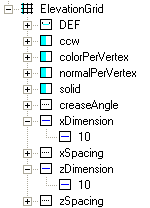
The ElevationGrid command creates a node that specifies a uniform
rectangular grid of varying height in the Y=0 plane of a local coordinate system.
The ![]() toolbar button and the ElevationGrid menu item are associated with this command.
toolbar button and the ElevationGrid menu item are associated with this command.
The initial field values of xDimension and zDimension, which indicate the numbers of elements of the grid height array in the X and Z directions, are 0, 0.
To change xDimension value, expand the
![]() field item in Tree View, see an example shown in figure
5, click its leaf item to activate its in-place editor, and input one (1)
integer number.
field item in Tree View, see an example shown in figure
5, click its leaf item to activate its in-place editor, and input one (1)
integer number.
 |
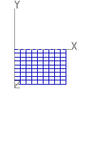 |
Figure 5 A grid after setting xDimension and xDimension fields
To specify per-vertex or per-quadrilateral colors for an ElevationGrid node, set the value of colorPerVertex in Tree View, see figure 6.
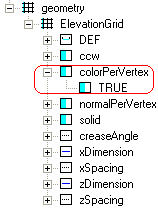
Figure 6 Setting a colorPerVertex field value in Tree View
To set each vertex has a normal attribute or a quadrilateral does, edit the normalPerVertex field in Tree View, see figure 7.
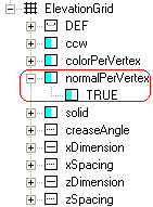
Figure 7 Setting a normalPerVertex field value in Tree View
To set distance between neighboring lines in X or Z direction, click the xSpacing or zSpacing field tree item to bring up the in-place editor in Tree View, and input a positive floating-point number.
In a Design View, to edit the height, do the following steps.
Check the Transformation section in Chapter Design View for further information.
In the Tree View, to edit the height field values, click the tree item to bring up an MFField editor.
For how to set other rendering properties, like ccw, convex, solid, and creaseAngle fields, check part Set common geometry fields in this chapter.
The function of the Extrusion command is to create
a geometric shape based on a two-dimensional cross-section line extruding along a
three-dimensional spine in a local coordinate system. The cross-section can be scaled
and rotated at each spine point to produce a wide variety of shapes. The
![]() toolbar
button and the Extrusion menu item are associated with this command.
toolbar
button and the Extrusion menu item are associated with this command.
 |
 |
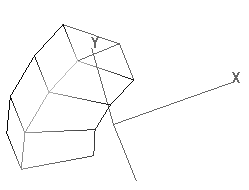 |
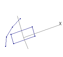
Figure 8 Building an Extrusion node from a Polyline2D and a LineSet node
In a Design View, to create an Extrusion node, follow the steps below.
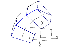
Figure 9 An Extrusion node and its original geometries
There is no sequence requirement whether the Polyline2D node or the LineSet should be created first, and there is no sequence requirement which one should be selected first when building an Extrusion node. Click here to see two lines and their extrusion code.
Optional operations can be added to the generated node.
To set whether the sides, the beginning cap and the end cap are created, edit the side, beginCap, and endCap fields in Tree View. The operation is similar to that of the solid field.
For how to set other rendering properties, like ccw, convex, solid, and creaseAngle fields, check the part Set common geometry fields in this chapter.
This modeler provides four (4) visual commands to scale Shape nodes: Scale X, Scale Y, Scale Z, and Scale, which are described in the Design View chapter.
There are 4 steps to scale an Extrusion geometry.
In the drag-and-drop step, the deformation starts from the endCap —the scale field at the endCap changes the most and it remains unchanged at the startCap. However, if the Shift key is pressed down, the deformation format goes to another side.
The following are different methods to edit the scale field values to make an extrusion node scaled about the origin:
For example, a spine curve has 4 points, defined as:
spine [ -5.188 -0.911 0, -4.319 2.653 0, -2.099 5.663 0, 0.515 7.881 0]
The scale field can be modified like this:
scale [1 1, 1 1, 1 1, 1.5 1.5]
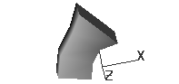
Figure 10(a) A scaled extrusion geometry whose last cross section plan (endCap) is enlarged 1.5 times.
![]()
Figure 10(b) scale field values in the MFField editing dialog box
Twist and Bend operations may result from editing orientation field values. Four (4) visual commands support it: Rotation X, Rotation Y, Rotation Z, and Arbitrary Rotation, which are described in the Design View chapter. Which command results in Twist and which one does a Bend operation depends on geometry axis direction. However, please note that the most powerful Bend operation is to edit the LineSet geometry. Figure 11 shows an example of how Rotation Y command is used to twist a bar.
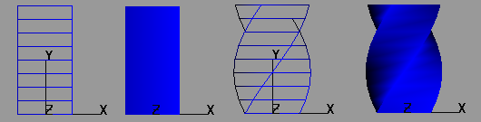
Figure 11 Twist operation results from Rotation Y command
There are 4 steps to twist or bend an Extrusion geometry.
In the drag-and-drop step, the deformation starts from the endCap —the orientation field at the end cap changes the most and it remains unchanged at the start cap. However, if the Shift key is pressed down, the deformation format goes to another side.
In Tree View and Code View, the orientation field values can also be edited.
Each orientation element has 4 floating-point numbers (x, y, z, a). X, y, and z define a normalized rotation axis vector about which the rotation takes place. The fourth number specifies the rotation angle in radians. In the following example, the endCap is rotated 0.4 radian about axis (0, 0, 1).
orientation [ 0 0 1 0, 0 0 1 0, 0 0 0 0,0 0 1 0.4,]
The function of the IndexedFaceSet command is to create
a geometric shape based on constructing facesets (polygons) from a set of coordinates
in a local coordinate system. Figure 12 is an example of the node, which
contains 6 triangles. The
![]() toolbar
button and the IndexedFaceSet menu item are associated with this
command.
toolbar
button and the IndexedFaceSet menu item are associated with this
command.
Normally, the IndexedFaceSet node is generated from other node(s), such as NURBS, sphere, et al. But in some cases, creating an IndexedFaceSet from points and facesets can still be hopeful.
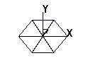
Figure 12 An IndexedFaceSet node that contains 6 triangles
To add points to the node, click the left mouse button in a Design View that can catch points and lines.
If the cursor hits no points, the cursor's shape is an arrow. When users press down the left button, a new point is added to the node.
If the cursor hits a point or a line of the node, the cursor's shape changes to a cross, and Design View catches the coordinate value. When users press down the left button, a copy of the coordinate value is added to the node.
Press the Enter key to end a face set editing and start a new one; press the Esc key to escape the process.
To edit the created points of the facesets in this node, see how to Edit points in the Rendering chapter.
To edit the normal field, see Normal section in the Rendering chapter.
The normalIndex field defines each vertex or faceset normal index. Click the field tree item and bring up an MFField Editing dialog box.
To set each vertex has a normal attribute or a quadrilateral does, edit the normal field in Tree View. To bring up the TRUE-FALSE box, click the field tree item.
The process of editing colorPerVertex, color, and colorIndex fields is similar to that of the normalPerVertex, normal, and normalIndex respectively.
For how to set other rendering properties, like ccw, convex, solid, and creaseAngle fields, check the part Set common geometry fields in this chapter.
The following four (4) steps show how to use IndexedFaceSet to build a small pyramid.
Here are the X3D codes that were created by step 1, step 2, step 3, and step 4.
By default, the quadrilaterals of a geometry are created with a counterclockwise
ordering. Setting the ccw field to FALSE reverses the normal direction.
To change the setting, expand the
![]() ccw field item, whose parent is the geometry nod tree item, such as
ccw field item, whose parent is the geometry nod tree item, such as
![]() ,
click the leaf item to bring up the TRUE-FALSE box.
,
click the leaf item to bring up the TRUE-FALSE box.
The default value of this field is TRUE. To change the value, expand the
![]() convex field item, whose parent is a geometry nod tree item, such as
convex field item, whose parent is a geometry nod tree item, such as
![]() ,
click its leaf item to bring up the TRUE-FALSE box.
,
click its leaf item to bring up the TRUE-FALSE box.
To set the field value, expand the field item, whose parent is a
geometry nod tree item, such as
![]() ,
click its leaf item to bring up its in-place editor, and input
a floating-point number.
,
click its leaf item to bring up its in-place editor, and input
a floating-point number.
To set whether a geometry is visible when viewed from inside, in Tree View, expand the
![]() solid field item, whose parent is a geometry nod tree item, such as
solid field item, whose parent is a geometry nod tree item, such as
![]() and
and ![]() ,
click its leaf item to bring up the TRUE-FALSE box.
,
click its leaf item to bring up the TRUE-FALSE box.
For transformation, see the Transform command in the Grouping chapter and the Transformation commands in the Design View chapter.
Boolean operation allows users to build different real-like 3D worlds through basic geometries, such as box, cone, sphere, cylinder, and extruded shapes. This modeler provides 5 types of operations: Combine, Difference, Intersection, Exclusion, and Division. To use these functions, first select two geometrical objects, then activate one of the commands by pressing icons or menu items.
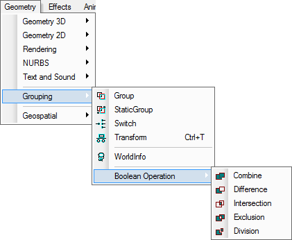
Figure 13 Boolean operation menu items

Figure 14 Boolean operation toolbar buttons
The function of this command is to combine two solid geometrical objects and it generates a new node, which normally discards obscure
partitions and reserves visible ones viewing from outside. The menu item Combine and the hot icon![]() are associated with this command.
are associated with this command.
The function of this command is to cut geometrical object A with geometrical object B, and it generates a new node,
which normally removes any partitions of A inside B. The menu item Difference and the hot icon
![]() are associated with this command.
are associated with this command.
The function of this command is to build a solid geometrical object using the public section(s) of two geometrical objects and
it generates a new node, which discards any partitions of A and B outside the shared public sections. The menu
item Intersection and the hot icon![]() are associated with this command.
are associated with this command.
The function of this command is to build a solid geometrical object by removing the public section(s) of two geometrical objects
and keeping not shared partitions. The menu item
Exclusion and the hot icon![]() are associated with this command.
are associated with this command.
The function of this command is to divide two solid geometrical objects A and B into three nodes, public section(s) of two geometrical objects, and not shared partitions of both A and B.
The menu item Division and the hot icon![]() are associated with this command.
are associated with this command.
The below image, figure 15, shows a cup pad which is made up of several small pieces of bamboo, see figure 16. To build the smallest unit, we used the following steps.
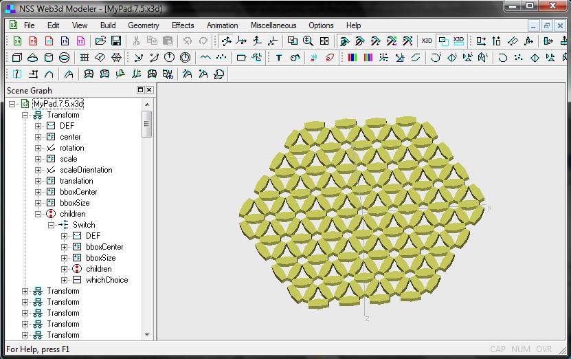
Figure 15 My Cup Pad
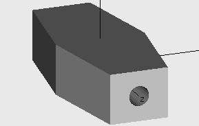
Figure 16 A small unit of My Cup Pad
Step 1: Create two cylinders and translate them along x-coordinate, see file MyPad.1.x3d.
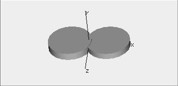
Figure 17 Two (2) cylinders as basis geometry nodes are used for Boolean operations
Step 2: Select the two cylinders and then activate Intersection command, and it generates a small block A, see file MyPad.2.x3d.
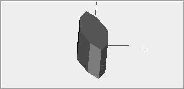
Figure 18 Intersection results
Step 3: Add a box to the scene, see file MyPad.3.x3d.
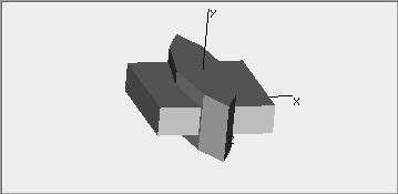
Figure 19 A box is added to scene for Boolean operation
Step 4: Select the box and the small block A, and activate the command Intersection, it generates a small block B. Check file MyPad.4.x3d.
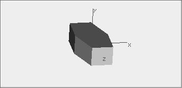
Figure 20 Boolean operation results
Step 5: Add a cylinder node to the scene and rotate it, see file MyPad.5.x3d.
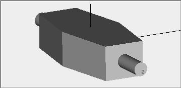
Figure 20 Another cylinder is added to screen for Boolean operations
Step 6: Select the cylinder and block B, and activate the Difference command, it generates a block C, as picture 16.