The following commands create geometries and their properties: IndexedLineSet, IndexedTriangleFanSet, IndexedTriangleSet, IndexedTriangleStripSet, LineSet, PointSet, TriangleFanSet, TriangleSet, TriangleStripSet, Color, ColorRGBA, Coordinate, Normal, and ClipPlane.
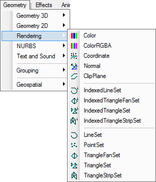
The menu items shown in figure 1 and toolbar buttons in figure 2 are associated with these commands.
Figure 1 The menu items for creating Rendering nodes
![]()
Figure 2 The toolbar buttons for Rendering nodes creation commands
IndexedLineSet, Color, Coordinate, and Normal are accessible when editing NSS Models, and Classic VRML and 2 Models, but other rendering nodes creation commands do not support VRML97 specifications.
This command creates an IndexedLineSet node contained in a Shape
node. The![]() toolbar button and the IndexedLineSet menu item are associated with this command.
toolbar button and the IndexedLineSet menu item are associated with this command.
This kind of geometric node is made up of polygons, an IndexedLineSet geometry's polygon set is initialized to zero (0) and coordinate set zero (0).
In a Design View, to add points to an IndexedLineSet node, click the left mouse button at proper position. This operation is similar to that of IndexedFaceSet; the coordIndex field records the updating.
Figure 3 shows an example of this kind of node.
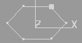
Figure 3 A polygon formed IndexedLineSet node
To start a new polygon, press the Enter key.
To escape adding polygons to the geometry, press the Esc key.
This command creates an IndexedTriangleFanSet node contained in a Shape
node whose triangle fan size is initialized to zero (0) and coordinate set zero (0). The![]() toolbar button and the IndexedTriangleFanSet menu item are associated with this command.
toolbar button and the IndexedTriangleFanSet menu item are associated with this command.
In a Design View, to add a triangle fan to an IndexedTriangleFanSet node, click the left mouse button. The operation is similar to that of IndexedFaceSet; the coordIndex field records the updating.
Figure 4 shows an example.
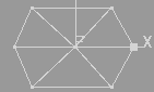
Figure 4 An IndexedTriangleFanSet geometry
To start a new triangle fan, press the Enter key.
To escape adding triangles to the geometry, press the Esc key.
This command creates an IndexedTriangleSet node contained in a Shape
node whose triangle set is initialized to zero (0) and coordinate set zero (0). The![]() toolbar button and the IndexedTriangleSet menu item are associated
with this command.
toolbar button and the IndexedTriangleSet menu item are associated
with this command.
In a Design View, to add triangles to an IndexedTriangleSet node, click the left mouse button. The operation is similar to that of IndexedFaceSet; the coordIndex field records the updating.
Figure 5 shows an IndexedTriangleSet node example.
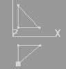
Figure 5 An IndexedTriangleSet geometry
To escape adding triangles to the geometry, press the Esc key.
This command creates an IndexedTriangleStripSet node contained in a Shape
node whose triangle strip size is initialized to zero (0) and coordinate set null. The![]() toolbar button and the IndexedTriangleSet menu item are associated with the command.
toolbar button and the IndexedTriangleSet menu item are associated with the command.
In a Design View, to add triangle strips, click the left mouse button. The operation is similar to that of IndexedFaceSet; the coordIndex field records the updating.
Figure 6 shows an IndexedTriangleStripSet node example.
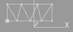
Figure 6 An IndexedTriangleStripSet geometry
To start a new triangle fan, press the Enter key.
To escape adding triangle strips to the geometry, press the Esc key.
This command creates a LineSet node contained in a Shape node whose polygon set is initialized to zero (0) and coordinate set zero (0). The![]() toolbar button and the LineSet menu item are associated with this command.
toolbar button and the LineSet menu item are associated with this command.
In a Design View, to add lines to a LineSet node, click the left mouse button. The operation is similar to that of IndexedFaceSet.
Figure 7 shows a LineSet node example.
Figure 7 A polygon formed LineSet node
To start a new polygon, press the Enter key.
To escape adding points to the geometry, press the Esc key.
This command creates a PointSet node contained in a Shape node
whose point set is initialized to null. The![]() toolbar button and the PointSet menu item are associated with this command.
toolbar button and the PointSet menu item are associated with this command.
In a Design View, to add points to an activated PointSet node, click the left mouse button. This operation is similar to that of IndexedFaceSet.
Figure 8 shows a PointSet node example.
![]()
Figure 8 A polygon formed PointSet
To escape adding points to the geometry, press the Esc key.
This command creates a TriangleFanSet node contained in a Shape
node whose triangle fan set is initialized to null and coordinate set null. The![]() toolbar button and the TriangleFanSet menu item are associated with
this command.
toolbar button and the TriangleFanSet menu item are associated with
this command.
In a Design View, to add triangle fans to an activated TriangleFanSet node, click the left mouse button. This operation is similar to that of IndexedFaceSet.
Figure 9 shows a TriangleFanSet node example.
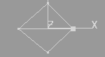
Figure 9 A TriangleFanSet geometry
To start a new triangle fan, press the Enter key.
To escape adding triangles to the geometry, press the Esc key.
This command creates a TriangleSet node contained in a Shape node whose triangle set is initialized to null and coordinate null. The![]() toolbar button and the TriangleSet menu item are associated with
this command.
toolbar button and the TriangleSet menu item are associated with
this command.
In a Design View, to add triangles to a TriangleSet node, click the left mouse button. This operation is similar to that of IndexedFaceSet.
Figure 10 shows a TriangleSet example.
![]()
Figure 10 A TriangleSet geometry
To escape adding triangles to the geometry, press the Esc key.
This command creates a TriangleStripSet node contained in a Shape
node whose triangle strip set is initialized to null and coordinate null.
The![]() toolbar button and the TriangleSet menu item are associated with this command.
toolbar button and the TriangleSet menu item are associated with this command.
In a Design View, to add strips to an activated TriangleStripSet node, click the left mouse button. This operation is similar to that of IndexedFaceSet.
Figure 11 shows a TriangleStripSet node example.
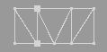
Figure 11 A TriangleStripSet geometry
To start a new triangle strip, press the Enter key.
To escape adding triangle strips to the geometry, press the Esc key.
This command creates a Color node.
The![]() toolbar button and the Color menu item are associated with this command.
toolbar button and the Color menu item are associated with this command.
This command creates a ColorRGBA node. The![]() toolbar button and the ColorRGBA menu item are associated with this command.
toolbar button and the ColorRGBA menu item are associated with this command.
This command creates a Coordinate node. The![]() toolbar button and the Coordinate menu item are associated with this command.
toolbar button and the Coordinate menu item are associated with this command.
This command creates a Normal node.
The![]() toolbar button and the Normal menu item are associated with this command.
toolbar button and the Normal menu item are associated with this command.
In general, it is not necessary to manually add a Normal node to a Shape node. This modeler automatically creates and attaches a Normal node to a Shape node if necessary.
The users can control the Modeler to output Normal nodes.
In the Options menu, there is an item Do not Write Normal. When users click on the item, it switches to Write Normal state. In the first state, the default state, the Modeler does not output Normal code, and the generated NSS code files are smaller. In the second state, the Modeler writes Normal values and the generated NSS files are bigger.
In order to control an individual Normal node code output, Tree View provides a popup menu, see figure 12. To bring up the popup menu, click on a Normal node tree item. When the Normal node has no text code, that is, its values are not recorded in a code file, Erase Normal Code item is grayed. When the Normal node has text code, the Write Normal Code item is grayed.
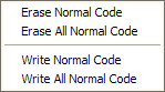
Figure 12 The Normal menu
The Normal menu provides Erase All Normal Code and Write All Normal Code commands, by which users can delete or write all Normal nodes.
This command creates a ClipPlane node that defines a plane with four (4) floating point numbers for clipping scene geometries.
The![]() toolbar button and the ClipPlane menu item are associated with this command.
toolbar button and the ClipPlane menu item are associated with this command.
These Rendering 3D nodes mentioned above have an important data element, point or Coordinate, which makes up the line segments, polygons, triangle strips, triangle fans, or triangles of the geometric nodes. Design View provides visual tools to insert, delete, and transform points.
To insert points into a Rendering 3D node mentioned above, first create the node using these commands described in sections 1~9, then use the following methods.
When a node is in an activated state, the insertion command is automatically enabled; to insert points, click with the left mouse button in a Design View to catch a point and add the coordinate information into the geometry.
When the node is no longer in activated state, to insert points, select the node either by Tree View commands or by Design View commands, and activate the Point command whose menu item is on the Build menu, see figure 13. When the command is activated, the menu item has a check mark, click the left mouse button in a Design View to get a point and add its coordinate information into the geometry.
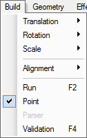
Figure 13 The Point menu item
When the mouse cursor hits a point image in a Design View, the mouse cursor shape changes to a cross. If the mouse clicks there, the position is picked up as the last point coordinate.
This command also allows users to insert points on a line into some special type geometries. Check the Knot insertion section for more details.
To delete points of a rendering 3D node mentioned above, follow the four (4) steps below.
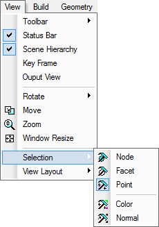
Figure 14 The Selection mode menu items
To transform points of a rendering 3D node mentioned above, follow the steps below.
See the Primary 3D chapter for how to set ccw, solid, convex, and creaseAngle field values.