
Design View provides a set of visual commands and drag-and-drop methods, which allow users to create and edit X3D world scenes.
This chapter gives a general description on how to use the creation interface elements and editing commands in design contexts. Check Part 3, Part 4, Part 5, and Part 6 for how to use specific node creation commands and editing tools to build virtual scenes.
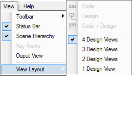
The View Layout commands that include Code, Design, and Code+Design, control whether a Design View is active, or a Code View is active, or both of them are accessible. Figure 1 shows the View Layout menu items and figure 2 shows the toolbar buttons associated with the View Layout commands.
Figure 1 The View Layout menu items
![]()
Figure 2 The View Layout toolbar buttons
To switch to Design View, choose the Design item or press the
![]() toolbar button. When selected, the Design menu item
has a check mark
toolbar button. When selected, the Design menu item
has a check mark![]() ,
and the
,
and the ![]() toolbar button has a shadow.
toolbar button has a shadow.
To switch to Code View, choose the Code item or press the
![]() toolbar button.
When selected, the Code menu item has a check mark
toolbar button.
When selected, the Code menu item has a check mark![]() , and the
, and the
![]() toolbar button has a shadow.
toolbar button has a shadow.
To make both Design View and Code View accessible, click the Code+Design
menu item or the
![]() toolbar button. When selected, the Code+Design menu item has a check mark
toolbar button. When selected, the Code+Design menu item has a check mark
![]() ,
and the
,
and the
![]() toolbar button has a shadow.
toolbar button has a shadow.
The Design View provides different tools to select geometry nodes and their properties, figure 3 shows the Selection menu items and figure 4 shows their toolbar buttons.
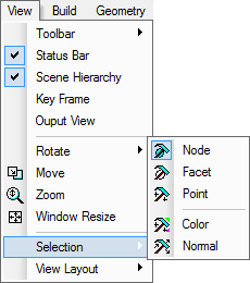
Figure 3 The Selection menu items
![]()
Figure 4 The Selection toolbar buttons
The Node item on the Selection sub-menu and the
![]() toolbar button are associated with the Select Nodes command, which allows users
to select geometry-based Shape nodes.
toolbar button are associated with the Select Nodes command, which allows users
to select geometry-based Shape nodes.
To select or clear a Shape node, do the steps below.
If the Ctrl key is down when operating, the last selection or un-selection is added to the previous set; otherwise, the previous selection set is cleared.
To select a set of Shape nodes, do the steps below.
The Facet item on the Selection sub-menu and the
![]() toolbar
button are associated with the Select Facets command, which allows users to select
facets of a Shape node.
toolbar
button are associated with the Select Facets command, which allows users to select
facets of a Shape node.
To select a set of facets, do the steps below.
The Point item on the Selection sub-menu and the
![]() toolbar
button are associated with the Select Points command, which provides a tool to select points.
toolbar
button are associated with the Select Points command, which provides a tool to select points.
To select points of a geometry, first select the geometry node, then activate the Select Points command.
Hold left mouse button down, drag and draw a rectangle; the points whose images fall into the rectangle will be selected.
This version still does not support this command. To edit colors, use Code View or Tree View.
This version still does not support this command. To edit normal, use Code View or Tree View.
This Web3d Modeler has tens of toolbar buttons and menu items for creating X3D built-in nodes that X3D specs define. To create an X3D node, click a node creation menu item or a toolbar button. This Modeler inserts the node into Scene Graph using the general rules:
For more detailed information on node creation commands, check part 3, part 4, part 5, and part 6.
Transformation commands fall into four (4) classes: Translation, Rotation, Scale, and Alignment. Figure 5 shows the menu items and figure 6 shows the toolbar buttons associated with these commands.
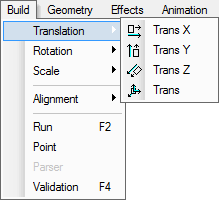
Figure 5(a) The Translation menu items
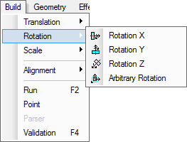
Figure 5(b) The Rotation menu items
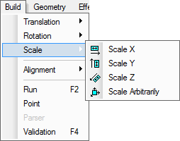
Figure 5(c) The Scale menu items
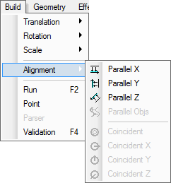
Figure 5 (d) The Alignment menu items
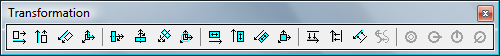
Figure 6 The Transformation toolbar buttons
To escape from these commands, press the esc key.
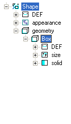
If a geometry-based Shape node is a root one, or it is contained in a Grouping node but not a Transform, to be transformed, the Shape must be moved into a Transform node. The following shows the steps:
Figure 7 shows an example; for more information about how to use the Transform command, check the Grouping chapter.
 |
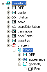 |
Figure 7 An image mapped Box node and the transformed Scene Graph
This command is used to rotate selected nodes about a given center at arbitrary
direction with the left mouse button. The rotation center is determined by the node’s
transformation hierarchy. The Arbitrary Rotation item on the Rotation
menu and the
![]() toolbar button are associated with this command.
toolbar button are associated with this command.
To rotate nodes, follow the below four (4) steps.
This command is used to rotate selected nodes about the x-axis with the left
mouse button. The rotation center is determined by the node’s transformation hierarchy.
The Rotation X menu item on the Rotation menu and the
![]() toolbar
button are associated with this command.
toolbar
button are associated with this command.
The operation of rotating objects around the x-axis is similar to that of Arbitrary Rotation except the rotation axis may be different.
This command is used to rotate selected nodes about the y-axis with the mouse
button. The rotation center is determined by the node’s transformation hierarchy. The
Rotation Y item on the Rotation menu and the
![]() toolbar
button are associated with this command.
toolbar
button are associated with this command.
The operation of rotating objects around the y-axis is similar to that of Arbitrary Rotation except the rotation axis may be different.
This command allows users to rotate selected nodes about the z-axis with the left
mouse button. The rotation center is determined by the node’s transformation hierarchy.
The Rotation Z item on the Rotation menu and the
![]() toolbar
button are associated with this command.
toolbar
button are associated with this command.
The operation of rotating objects around the z-axis is similar to that of Arbitrary Rotation except the rotation axis may be different.
This command allows users to translate selected nodes along the x-axis with the left
mouse button. The Move X item on the Translation menu and the
![]() toolbar
button are associated with this command.
toolbar
button are associated with this command.
To translate nodes, follow the below four (4) steps.
This command allows users to translate selected nodes along the y-axis with the left
mouse button. The Trans Y item on the Translation menu and the
![]() toolbar
button are associated with this command.
toolbar
button are associated with this command.
This kind of operation is similar to that of Trans X except this translation happens in a different direction.
This command allows users to translate selected nodes along the z-axis with the left
mouse button. The Trans Z menu item on the Translation menu and the
![]() toolbar button are associated with this command.
toolbar button are associated with this command.
This kind of operation is similar to that of Trans X except this translation happens in a different direction.
This command allows users to translate selected nodes with the mouse button. The Trans item on the Translation menu and the
![]() toolbar
button are associated with this command.
toolbar
button are associated with this command.
This kind of operation is similar to that of Trans X except this translation may be in a different direction.
This command allows users to scale selected nodes along the x-axis with the left
mouse button. The Scale X item on the Scale menu and the
![]() toolbar button are associated
with this command.
toolbar button are associated
with this command.
To scale node(s), follow the below four (4) steps.
 toolbar button.
This command allows users to scale selected nodes along the y-axis with the left
mouse button. The Scale Y item on the Scale menu and the
![]() toolbar
button are associated with this command.
toolbar
button are associated with this command.
This kind of operation is similar to that of Scale X, but the results are different.
This command allows users to scale selected nodes along the z-axis with the mouse
button. The Scale Z item on the Scale menu and the
![]() toolbar
button are associated with this command.
toolbar
button are associated with this command.
This kind of operation is similar to that of Scale X, but the results are different.
This command allows users to scale selected nodes with the left mouse button. The
Scale Arbitrarily item on the Scale menu and the
![]() toolbar
button are associated with this command.
toolbar
button are associated with this command.
This kind of operation is similar to that of Scale X, but the results may be different.
This command makes selected objects parallel to the x-axis. The Parallel X
item on the Alignment menu and the
![]() toolbar
button are associated with this command.
toolbar
button are associated with this command.
To parallel Shape node(s), follow the below three (3) steps.
This command makes selected nodes parallel to the y-axis. The Parallel Y
item on the Alignment menu and the
![]() toolbar
button are associated with this command.
toolbar
button are associated with this command.
This kind of operation is similar to that of Parallel X, but their results are different.
This command makes the selected node(s) parallel to the z-axis. The Parallel Z
item on the Alignment menu and the
![]() toolbar
button are associated with this command.
toolbar
button are associated with this command.
This kind of operation is similar to that of Parallel X, but their results are different.
This command makes selected nodes parallel to each other. The Parallel Obis
item on the Alignment menu and the
![]() toolbar button
are associated with this command.
toolbar button
are associated with this command.
This kind of operation is similar to that of Parallel X, but results may be different.
This command makes selected nodes a coincidence. This command is only valid for Shape nodes whose parents are Transform nodes. The Coincident item on the Alignment menu and the ![]() toolbar button
are associated with this command.
toolbar button
are associated with this command.
To make the nodes coincide, follow the steps below.
This command makes selected nodes aligned to x=a plane. This command is only valid for Shape nodes whose parents are Transform nodes. The Coincident X item on the Alignment menu
and the ![]() toolbar button
are associated with this command.
toolbar button
are associated with this command.
This kind of operation is similar to that of Coincident, but their results are different.
This command makes selected nodes aligned to y=a plane. This command is only valid for Shape nodes whose parents are Transform nodes. The Coincident Y item on the Alignment menu
and the ![]() toolbar button
are associated with this command.
toolbar button
are associated with this command.
The operation of this command is similar to that of Coincident, but their results are different.
This command makes the selected nodes aligned to z=a plane. This command is only valid for Shape nodes whose parents are Transform nodes. The Coincident Z item on the Alignment menu
and the ![]() toolbar button
are associated with this command.
toolbar button
are associated with this command.
The operation of this command is similar to that of Coincident, but their results are different.
The Ctrl+X shortcut key executes the Delete command, which deletes selected node(s) or other elements, such as points.
See the Selection paragraph in this chapter and the Selection in the Tree View chapter for how to select nodes, points, and other elements.
A set of options are available, which allow users to configure Design Views and viewing properties.
A window can be divided into 1, 2, 3, or 4 partitions, each partition establishes a Design View. Figure 8 shows the View Layout menu items, which allow users to configure the view number. The left image shows mainframe menus when this Modeler starts, and the right part shows a different state when this Modeler is editing a virtual world.
 |
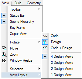 |
Figure 8 The View Layout menu items
Users can choose Design View number by the commands: 4 Design Views, 3 Design Views, 2 Design Views, and 1 Design View. Figure 9 shows a window divided into 4 Design Views. By default, each view has a coordinate system symbol, a thin frame, and background grid lines.
To hide or show the coordinate system symbol, press ALT+C. The Context Menu has the Enable/Disable Coordinate System Symbol item, which also provides hide and show commands.
To change the background grid line colors, follow the steps below.
To hide or show the background gridlines, press ALT+R. The Context Menu has the Enable/Disable Background Grid item, which also provides hide and show commands.
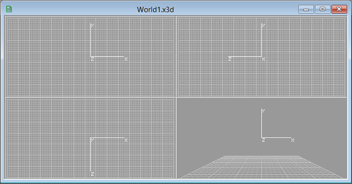
Figure 9 A window is divided into four (4) Design Views
Different viewpoints are available for displaying virtual worlds; a Design View can be set as: left side view, right side view, top view, bottom view, front view, rear view, or a camera view.
To choose a viewing type for a Design View, move the cursor onto the Design View, click with the right mouse button to bring up a context menu which includes viewing type items, see figure 10 as an example. Move the cursor over an item, click the left mouse button to set the viewing type or press the Esc key to cancel the setting.
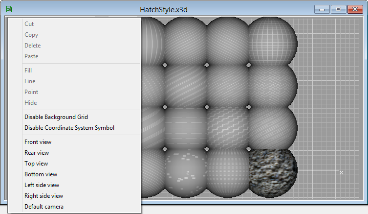
Figure 10 The context menu items for selecting a viewing type
The size of a Code View and a Design View can be changed. The Window Resize item on the View menu and the
![]() toolbar button are associated with this command.
toolbar button are associated with this command.
To resize the windows, follow the steps below.
This command sets the background color for Design View. The Background Color item on the Options|Font, Color menu, see figure 11, is associated with this command.
To change the background color, follow the steps below.
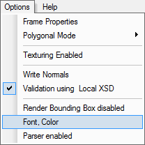
Figure 11 The Options menu
This command sets the color for rendering selected geometries. The Selection Color item on the Options|Font, Color menu is associated with this command.
The Color list contains the Selected Geometry item, select it and press Select color button to bring up the color selection dialog box.
To change the rendering color, pick up a color and press the OK button in this dialog window. Press the Cancel button or the Esc key to cancel the setting. See the Color dialog box paragraph in the Tree View chapter for more information.
Four (4) options are available for rendering a geometry: Full (Ctrl+Shift+S), Line (Ctrl+Shift+L), Point (Ctrl+Shift+P), and Hide (Ctrl+Shift+H).
To set a rendering mode for selected Shape nodes, users can press the shortcut keys in Design View, or,
The Full option lets the geometry be rendered as defined in X3D specs; the Line option lets the geometry be rendered as lines; the Point option lets the geometry be rendered as a set of points. The Hide option disables the geometry from rendering.
A virtual world can have some frames, and the world may change from one frame to the next when an X3D Browser plays the world. The Frame Properties menu item on the View menu allows users to show or hide a key frame window by which the time-based sequence for playing the virtual world can be defined.
Figure 12 shows a Key frames window. The window is horizontally divided into some partitions, each partition has two rectangles occupying the up and down part. A colored slider is an indicator, which can be dragged with the left mouse button from one partition to another.
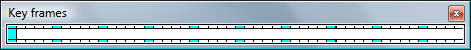
Figure 12 Key frame dialog box
Frame Properties command provides a dialog box by which users can set partition size. Clicking the Frame Properties menu item on the Options menu brings up a window whose image is shown in figure 13. Input a floating-point number in the Start box, and the End box receives a floating-point value too. In the Partition box, input an integer value.
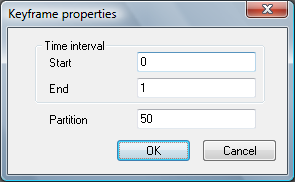
Figure 13 Keyframe properties dialog box
X3D interpolator nodes like ScalarInterpolator and PositionInterpolator have the key field that can inherit values from the Key frames window: the first value of the key equals to the Start in the Keyframe properties window, the last value equals to the End, and other values are calculated by its frame position. Check Normalization in the Events chapter for how to use the frame properties.
The Parser Results command lets users review the results of the last parsing. The results are displayed in the Output View.
The Texturing Disabled command allows users to decide a texturing option for an active view: enable or disable. By this way, users can choose objects and set them rendered with or without textures in a given view.
The Write Normal option allows users to control whether Normal field values are printed or not in Code View.
This command launches an external X3D browser to explore the current X3D content. To Run this function, it is necessary to install an X3D browser or an application.
This command calls the internal parser and parses the current X3D content. After the user edits the X3D content in Code View and wants to check the content, this command can be activated. However, in most cases, it is not necessary to click the menu item Parser, because this command is automatically activated and scans X3D code regularly. This command has a hotkey: Ctrl+B.
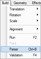
Figure 14 The Parser menu item
The following commands are available in Design Views, and they differ from Transformation commands: Transformation commands change virtual world nodes properties, such as size and position, when the View commands allow users to check the virtual world at different views but do not change any properties of the virtual world nodes.
This Modeler provides four (4) commands to rotate the view: Track Ball![]() , Rotate X
, Rotate X![]() , Rotate Y
, Rotate Y![]() , and Rotate Z
, and Rotate Z![]() .
See figure 15 for their menu items. Track Ball assumes that a ball encloses the virtual world, and the cursor touches the ball and rotates the view; Rotate X, Rotate Y, and Rotate Z
commands allow users to rotate the view along x, y, and z-axis.
.
See figure 15 for their menu items. Track Ball assumes that a ball encloses the virtual world, and the cursor touches the ball and rotates the view; Rotate X, Rotate Y, and Rotate Z
commands allow users to rotate the view along x, y, and z-axis.
To rotate the view, first activate the command either by menu item or toolbar icon, then move the cursor into a Design View and drag-and-drop the view.
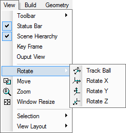
Figure 15 The menu items for rotating the views
NSS Web3d Modeler provides two (2) kinds of centers for rotation: coordinate system origin and virtual world center. By default, this modeler uses coordinate system origin. When keyboard key Caps Lock is toggled on or the alt key is pressed down when rotation happens, the virtual world center, the window center, is used.
The Move![]() command allows users to move the view.
command allows users to move the view.
To move the view, first activate the command either by menu item or toolbar icon, then move the cursor into a Design View and drag-and-drop the view.
The Zoom![]() command allows users to scale the view.
command allows users to scale the view.
To scale the view, first activate the command either by menu item or toolbar icon, then move the cursor into a Design View and drag-and-drop the view in up-down direction. Down pulls objects nearer. To speed up scaling, hold down the ALT key.
This command matches user programmed X3D-XML code with X3D specifications. After the user edits the X3D content in Code View and wants to validate the content, this command can be activated. This command has a in Design view hotkey: F4.
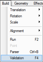
Figure 16 The Validation menu item