
Event utilities, which gate, convert, or sequence node behaviors, are used to build general interactive applications. Here are event utility commands support X3D worlds: BooleanFilter, BooleanSequencer, BooleanToggle, BooleanTrigger, IntegerSequencer, IntegerTrigger, TimeTrigger, Script, and Route. The toolbar buttons shown in figure 1, and menu items in figure 2 are associated with these commands.
Figure 1 The toolbar buttons for creating Event Utility nodes

Figure 2 The menu items for creating Event Utility nodes
These utility commands are accessible when editing X3D, Classic VRML, and VRML97 Models, but the first seven commands are not valid for VRML97 Models.
This command creates a BooleanFilter node. The
![]() toolbar button and the BooleanFilter menu item are associated with this
command. In a design environment, it is not necessary to set the node's field values,
except the node name.
toolbar button and the BooleanFilter menu item are associated with this
command. In a design environment, it is not necessary to set the node's field values,
except the node name.
This command creates a BooleanSequencer node. The
![]() toolbar button and the BooleanSequencer menu item are associated with this command.
toolbar button and the BooleanSequencer menu item are associated with this command.
To build a sequence, click the
![]() keyValue
field item to bring up the MFField
dialog box. See the Tree View chapter
for how to edit MFField field values. Figure 3 shows a BooleanSequencer
node formed Scene Graph.
keyValue
field item to bring up the MFField
dialog box. See the Tree View chapter
for how to edit MFField field values. Figure 3 shows a BooleanSequencer
node formed Scene Graph.

Figure 3 A BooleanSequencer node's tree items
This command creates a BooleanToggle node, which records a boolean value for toggling on/off. The
![]() toolbar button and the BooleanToggle menu item are associated with this command.
toolbar button and the BooleanToggle menu item are associated with this command.
To set the toggle field value, click the
![]() toggle
tree item to bring up the TRUE-FALSE box.
toggle
tree item to bring up the TRUE-FALSE box.
This command creates a BooleanTrigger node. The
![]() toolbar button and the BooleanTrigger menu item are associated with this
command. In a design environment, it is not necessary to set the node's field values, except the node name.
toolbar button and the BooleanTrigger menu item are associated with this
command. In a design environment, it is not necessary to set the node's field values, except the node name.
This command creates an IntegerSequencer node, which generates sequential SFInt32
events for a single TimeSensor clock. The
![]() toolbar button and the IntegerSequencer menu item are associated with this command.
toolbar button and the IntegerSequencer menu item are associated with this command.
To build a sequence, click the
![]() keyValue
tree item to bring up the MFField
dialog box. See the Tree View chapter
for how to edit MFField field values. Figure 4 shows an IntegerSequencer
node formed Scene Graph.
keyValue
tree item to bring up the MFField
dialog box. See the Tree View chapter
for how to edit MFField field values. Figure 4 shows an IntegerSequencer
node formed Scene Graph.
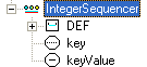
Figure 4 An IntegerSequencer node's tree items
This command creates an IntegerTrigger node, which sets an integer value for handling
single field Boolean events. The
![]() toolbar button and the IntegerTrigger menu item are associated with this command.
toolbar button and the IntegerTrigger menu item are associated with this command.
To set a value for the
![]() integerKey field, click the tree leaf item to activate
the in-place editor, and input an integer.
integerKey field, click the tree leaf item to activate
the in-place editor, and input an integer.
This command creates a TimeTrigger node, which generates time events for X3D applications.
The ![]() toolbar button and the TimeTrigger menu item are associated with this command.
In a design environment, it is not necessary to set the node's field values, except the node name.
toolbar button and the TimeTrigger menu item are associated with this command.
In a design environment, it is not necessary to set the node's field values, except the node name.
BooleanSequencer, IntegerSequencer, and Interpolator nodes have the key field, which records time based frame values. A function called Key normalization catches and saves these values for the above nodes: a range [t0, t1] and a partition number n. The range can be edited via a Frame Properties item on Options menu. The number n can be either the partition field value or the keyValue dimension, which depends on design contexts.
To activate this command, in Tree View, click the node's tree item, such as
![]() , to bring up a dialog box , and select the Normalize item.
, to bring up a dialog box , and select the Normalize item.

Figure 5 The Normalization dialog box
This command creates a Script node, which references programming language code via
the field url or contains ECMAScript code. The
![]() toolbar button and the Script menu item are associated with this command.
toolbar button and the Script menu item are associated with this command.
Check the URL section in the Tree View chapter for how to edit URL field values.
To write Script code, use Code View.
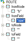
This command creates a ROUTE, which connects two fields and changes the values
of one field at runtime. The
![]() toolbar button and the Route menu item are associated with this command.
toolbar button and the Route menu item are associated with this command.
In Tree View, a ROUTE node has four items: fromNode, fromField, toNode, and toField. See figure 6 (left).
The fromNode and fromField records input information comes from which node and which field.
The toNode and toFielditem record the output information that is to be sent to which node and which field.
In Tree View, to set these values, follow the steps below.
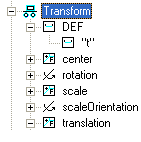
In the following example, a Transform node is named as "t", a Box is named as "b", our task is: setting b's size to t's translation field for run-time events.
To set the fromNode and fromField values, drag-and-drop the size field item to fromField tree item.
To set the toNode and toField values, drag-and-drop the translation field item to toField tree item.
The following table shows ROUTE tree states.
 |
 |
 |
 |
 |
Figure 6 Setting fromField and toFied field values in Tree View
Besides drag-and-drop, this modeler provides selection dialog boxes for the four fields: clicking a leaf tree item brings up a selection box that lists all available node names or node attribute names.