These commands allow users to create curves and surfaces: Contour2D, ContourPolyline2D, NurbsCurve2D, NurbsCurve, NurbsPatchSurface, NurbsSet, NurbsSweptSurface, NurbsSwungSurface, NurbsTextureCoordinate, NurbsTrimmedSurface, NurbsOrientationInterpolator, NurbsPositionInterpolator, and NurbsSurfaceInterpolator.
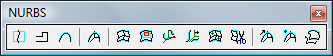
The toolbar buttons shown in figure 1 and menu items in figure 2 are associated with these commands.
Figure 1 The toolbar buttons for creating NURBS nodes
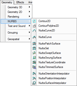
Figure 2 The menu items for creating NURBS nodes
This chapter explains how to use these commands to add curves and surfaces to a scene, and how to edit the nodes and their field values.
These commands are accessible when editing X3D and Classic VRML Models.
This command creates a Contour2D node that groups a set of curve segments to composite a contour. The
![]() toolbar button and the Contour2D menu item are associated with this command.
toolbar button and the Contour2D menu item are associated with this command.
This command attaches the Contour2D node to
See the Selection paragraph in the Design View chapter and the Selection paragraph in the Tree View chapter for how to select a node.

Figure 3 A Contour2D node's tree items
There are two methods to add a child node —a ContourPolyline2D node or a NurbsCurve2D — to a Contour2D node.
If a NurbsTrimmedSurface is selected along with other node(s) when this command starts, the created Contour2D node may not be attached to the NurbsTrimmedSurface node. This is to say, if users want to attach a Contour2D node to NurbsTrimmedSurface, do not select other nodes.
This command creates a ContourPolyline2D node that specifies a linear curve
segment as a part of a trimming contour in the u, v domain of a surface. The
![]() toolbar button and the ContourPolyline2D menu item are associated with this command.
toolbar button and the ContourPolyline2D menu item are associated with this command.
The command attaches a ContourPolyline2D node to
See the Selection paragraph in the Design View chapter and the Selection paragraph in the Tree View chapter for how to select a node.
![]()
Figure 4 A ContourPolyline2D node's tree items
To add line segments to a ContourPolyline2D node, first make the node activated or selected, then click the left mouse button. If the cursor hits no points, a new point whose image is displayed as a small spot will be added to the point field. If the cursor hits a point whose image is displayed as a big spot, then this point will be duplicated and the new copy will be added to the polygon. Figure 4 shows an example.
 |
 |
 |
 |
 |
Figure 5 Creating a ContourPolyline2D node
To escape this process, press the Esc key.
Check the Edit point section in the Rendering chapter for how to edit points.
This command creates a NurbsCurve2D node, which defines a trimming segment that
is part of a trimming contour in the u, v domain of a surface. The
![]() toolbar button and the NurbsCurve2D menu item are associated with this command.
toolbar button and the NurbsCurve2D menu item are associated with this command.
This command attaches the NurbsCurve2D node to
See the Selection paragraph in the Design View chapter and the Selection paragraph in the Tree View chapter for how to select a node.

Figure 6 A NurbsCurve2D node's tree items
The NurbsCurve2D command sets the mouse operation type to be Add control points, which allows users to add control points to the geometry.
If the cursor hits no points, a new point whose image is displayed as a small spot will be added to the point field. If the cursor hits a point whose image is displayed as a big spot, then this point is duplicated and the new copy will be added to the node. Figure 7 shows an example.
 |
 |
 |
 |
Figure 7 Creating a NurbsCurve2D node
To escape the process, press the Esc key.
To add control points to the node, make the node activated or selected, and then start the Add control points command, click the left mouse button.
Check the knot insertion section in this chapter for how to insert a knot/control point; check the Edit point section in the Rendering chapter for how to edit point.
The tessellation field defines how rough an application draws that curve. An integer value in the range of (-20, 20) may visually change a curve's appearance when using NSS Web3d Modeler: a bigger value, like 10, sets a curve smoother; a smaller value, for example -10, makes the curve rougher.
This command creates a NurbsCurve node contained in a Shape node, which specifies
a parametric curve in 3D space. The
![]() toolbar button and the NurbsCurve menu item are associated with this command.
toolbar button and the NurbsCurve menu item are associated with this command.
This command attaches the Shape node to
See the Selection paragraph in the Design View chapter and the Selection paragraph in the Tree View chapter for how to select a node.

Figure 8 A NurbsCurve node's tree items
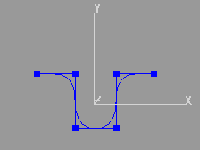
This command is similar to the NurbsCurve2D command, except that the latter creates two dimensional curves. Figure 9 shows a NurbsCurve with control points displayed (left) and hidden (right).
 |
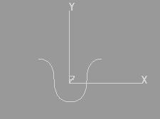 |
Figure 9 A NurbsCurve geometry
Check the knot insertion section in this chapter for how to insert knot/control points; check the Edit point section in the Rendering chapter for how to edit point positions.
The tessellation field defines how rough an application draws that curve. An integer value in the range of (-20, 20) may visually change a curve's appearance when using NSS Web3d Modeler: a bigger value, like 10, sets a curve smoother; a smaller value, for example -10, makes the curve rougher.
This command creates a NurbsPatchSurface node contained in a Shape node, which specifies a parametric surface
in 3D space. The ![]() toolbar button and the NurbsPatchSurface menu item are associated with this command.
toolbar button and the NurbsPatchSurface menu item are associated with this command.
This command attaches the Shape node to
See the Selection paragraph in the Design View chapter and the Selection paragraph in the Tree View chapter for how to select a node.

Figure 10 A NurbsPatchSurface node's tree items
By default, the order of a surface in the u and v dimensions is 3. To set a different value, follow the steps below.
By default, a NURBS geometry has no control points. To set the dimension size, expand the
![]() uDimension
and
uDimension
and
![]() vDimension
field item, click their leaf items to activate the in-place editor, and input
an integer value for each field. Resetting the uDimension or vDimension renews this node.
vDimension
field item, click their leaf items to activate the in-place editor, and input
an integer value for each field. Resetting the uDimension or vDimension renews this node.
Figure 11 shows a NurbsPatchSurface with 4X4 control points.
 |
 |
 |
 |
Figure 11 A NurbsPatchSurface geometry
When a NurbsPatchSurface is selected, a Design View displays control points and the points-formed grid. To edit a control point, click on the point to make it selected and it will be displayed as a big spot, and then drag-and-drop.
The uTessellation and vTessellation fields define how rough an application draws that surface. An integer value in the range of (-20, 20) may visually change a surface's appearance when using NSS Web3d Modeler: a bigger value, like 10, sets a curve smoother; a smaller value, for example -10, makes the surface rougher.
NSS Web3d Modeler ignores vTessellation field value when rendering, which means that uTessellation field value is used for rendering that kind of surfaces.
This command creates a NurbsSet node, which groups a set of NurbsSurface
nodes. When there are NurbsSurface nodes selected, these nodes will be moved
to the grouping node after NurbsSet command starts.
The ![]() toolbar button and the NurbsSet menu item are associated with this command.
toolbar button and the NurbsSet menu item are associated with this command.
A NurbsSurface can be one of these types: NurbsPatchSurface, NurbsSweptSurface, NurbsSwungSurface, and NurbsTrimmedSurface.
See the Selection paragraph in the Design View chapter and the Selection paragraph in the Tree View chapter for how to select a node.
See the Addition and deletion section in the Grouping chapter for how to add and delete a child.
This command creates a Shape node containing NurbsSweptSurface geometry —a cross
section curve sweeps along a 2D path curve. The
![]() toolbar button and the NurbsSweptSurface menu item are associated with this command.
toolbar button and the NurbsSweptSurface menu item are associated with this command.
There are three (3) steps to build a NurbsSweptSuface geometry.
This command attaches the geometry node to
See the Selection paragraph in the Design View chapter and the Selection paragraph in the Tree View chapter for how to select a node.
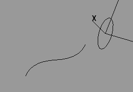
Figure 12 shows a 2D NURBS circle and a NURBS curve formed swept surface.
 |
 |
 |
Figure 12 Two (2) NURBS curves forms a NurbsSweptSurface
This command creates a Shape node containing NurbsSwungSurface
geometry —formed from a cross section curve and a path curve. The
![]() toolbar button and the NurbsSwungSurface menu item are associated with this command.
toolbar button and the NurbsSwungSurface menu item are associated with this command.
There are three (3) steps to build a NurbsSwungSurface geometry.
This command attaches the geometry node to
See the Selection paragraph in the Design View chapter and the Selection paragraph in the Tree View chapter for how to select a node.
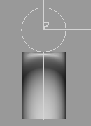
Figure 13 shows two examples of this kind of surface.
 |
 |
Figure 13 Two (2) NurbsSwungSurface examples
This command creates a NurbsTextureCoordinate node. The
![]() toolbar button and the NurbsTextureCoordinate menu item are associated with this command.
toolbar button and the NurbsTextureCoordinate menu item are associated with this command.
This command attaches the texture coordinate node to
See the Selection paragraph in the Design View chapter and the Selection paragraph in the Tree View chapter for how to select a node.
Figure 14 shows an example, a texture coordinate node is attached to a NurbsPathcSurface.

Figure 14 A textureCoordinate node is attached to a NurbsPatchSurface
This command creates a Shape-contained NurbsTrimmedSurface
node, a NURBS surface trimmed by a set of trimming loops stored in the trimmingContour field.
The ![]() toolbar button and the NurbsTrimmedSurface menu item are associated with this command.
toolbar button and the NurbsTrimmedSurface menu item are associated with this command.
This command catches selected trimming loops, Contour2D nodes formed from NurbsCurve2D and ContourPolyline2D —and a NurbsPatchSurface node. When there are some Contour2D nodes selected, this command copies the loops to the trimmingContour field.
If there are no selected loops nor surfaces, this command still creates a NurbsTrimmedSurface geometry. Trimming loops and a surface can be added to this node later.
This command attaches the geometry node to
See the Selection paragraph in the Design View chapter and the Selection paragraph in the Tree View chapter for how to select a node.
This command creates a NurbsOrientationInterpolator node, which specifies
a parametric curve in 3D space for interpolation purposes. The
![]() toolbar button and the NurbsOrientationInterpolator
menu item are associated with this command.
toolbar button and the NurbsOrientationInterpolator
menu item are associated with this command.
This command attaches the interpolator node to
The NurbsOrientationInterpolator node fields can be edited as that of a NurbsCurve node.
This command creates a NurbsPositionInterpolator node, which specifies
a parametric curve in 3D space for interpolation. The
![]() toolbar button and the NurbsPositionInterpolator menu item are associated with this command.
toolbar button and the NurbsPositionInterpolator menu item are associated with this command.
This command attaches the interpolator node to
The NurbsPositionInterpolator node fields can be edited as that of a NurbsCurve node.
This command creates a NurbsSurfaceInterpolator node,
which specifies a parametric surface in 3D space for interpolation. The
![]() toolbar button and the NurbsSurfaceInterpolator menu item are associated with this command.
toolbar button and the NurbsSurfaceInterpolator menu item are associated with this command.
This command attaches the interpolator node to
The NurbsSurfaceInterpolator node fields can be edited as that of a NurbsPatchSurface node.
To insert a control point to a node, do the following steps.
Figure 15 shows the Point command menu item. This command allows users to add or insert point to a geometry.
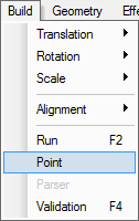
Figure 15 Point command menu item
In step 3, if the ctrl key is down, this modeler catches the nearest point on the control lines of a geometry. The point is floating and follows the cursor; to insert the point, click the left mouse button. The following images show the process. The left image shows 4 control points and a NurbsCurve; middle, a floating point (big spot), curve, and control points; right, the inserted point and a new curve.
 |
 |
 |
Figure 16 Inserting a Control Point
The Insert point on line function is applicable for these node types: NurbsCurve, NurbsCurve2D, LineSet, and ContourPolyline2D.